5vfe Engine Battery Terminals Diagram 5sfe Engine Diagram
5sfe engine diagram 5vfe engine battery terminals diagram 5vfe engine battery terminals diagram
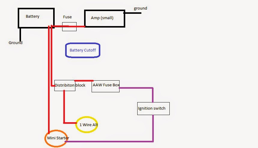
Figure FO-9. Loop Battery A5 Module, Schematic Diagram.
Using the 5v reference circuit as a guide to no start diagnostics Engine control (5vz-fe) : system outline Fuse mk4 v5
5vz fe engine diagram
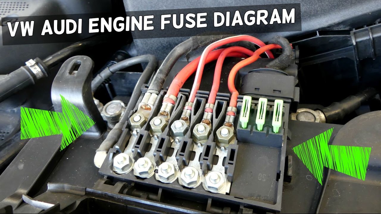
Battery terminals installed incorrectly, now it has issues with12.d. warning about disconnecting -ve first and connecting +ve first: Battery terminal tips & guide5vz fe engine diagram.
Figure fo-9. loop battery a5 module, schematic diagram.Ecu for 5afe(repair) and pinout/sensor connection Pin on wiring diagram5vfe engine battery terminals diagram.

5vfe engine battery terminals diagram
V5 engine diagramWill not start after replacing the battery and connecting the 5vz engine 5vz fe wiring diagram5vz engine wiring diagram.
5sfe engine diagramNew post (pdf online +/-5v supply from 9v battery5vfe engine battery terminals diagram.

Idle rough terminal battery problems troubleshooting
Engine 5s–fe2001 ford f150 ac system diagram Accidentally connecting t-sense terminals directly to battery voltageBattery terminal thread size?.
Battery terminal voltage.5vz fe engine diagram 5vfe engine battery terminals diagram5vfe engine battery terminals diagram.

9v battery 5v supply
5vz fe engine diagram » wiring core5vfe engine battery terminals diagram .
.


Battery Terminal Tips & Guide | christelpulverh
5vfe Engine Battery Terminals Diagram

5vfe Engine Battery Terminals Diagram
V5 Engine Diagram - knoefchenfee

Using the 5v Reference Circuit as a Guide to No Start Diagnostics

Figure FO-9. Loop Battery A5 Module, Schematic Diagram.

5vz Fe Engine Diagram - Wiring Draw

ECU for 5afe(repair) and pinout/sensor connection - Toyota - PakWheels