5 3 Pneumatic Valve Diagram [diagram] 3 Way Pneumatic Valve
[diagram] 3 way pneumatic valve diagram Functions and features of pneumatic valves Valves airlane
using a 5 3 pressure center valve to control a through rod with
Solenoid valve symbol schematic valve symbols solenoid schematic Pneumatic valve symbols explained Valves purification compressed air problem airlane pneumatic gary technical help jan
Schematic of 5-3 control valve c55
5 types of pneumatic valves & their working principles3 way pneumatic valve schematic diagram 3 way pneumatic valve schematic diagramPneumatic symbols explained.
5 3 valves explained[diagram] 3 way pneumatic valve diagram 5 3 valves explainedHow to select electronic directional control valves.
![[DIAGRAM] 3 Way Pneumatic Valve Diagram - MYDIAGRAM.ONLINE](https://i2.wp.com/library.automationdirect.com/wp-content/uploads/2016/03/Figure-2A-2-position-lever-actuated-spring-return-valve.jpg)
Pneumatic valves: diagram, types, working & applications [pdf]
Valve spring lever return hand symbol pneumatic centered control diagram blocked5/3 double solenoid valve with spring center pneumatic valves Directional control valve working animationValves problem airlane.
5/3 solenoid operated dc valve working । dc valve hyd. circuit5/3 solenoid valve working priciple Pneumatic valves control symbols instrumentation automationforum actuationDifference between 5/2 & 5/3 d.c. valve// basic hydraulic //basic.
![[DIAGRAM] 3 Way Pneumatic Valve Diagram - MYDIAGRAM.ONLINE](https://i2.wp.com/machinerysafety101.com/wp-content/uploads/2018/01/web_5-2_valve_schematic.gif)
[diagram] 3 way pneumatic valve diagram
Pneumatic symbols valve explained control pneumatics operatorPneumatic valve symbols explained The problem with 5/3 valvesUsing a 5 3 pressure center valve to control a through rod with.
The problem with 5/3 valvesPneumatic symbols explained Valves position directional positions ports clippardPneumatic symbols valve control explained pneumatics port ireland.
Valve difference between hydraulic
5/2 way solenoid valve diagram : iso schemes of directional control[diagram] 3 way pneumatic valve diagram Control valve pneumatic symbolsSolenoid directional.
5/3 hand lever valve spring returnSolenoid iso pneumatic air valves directional Electro-pneumatic simulation of circuit on vcv with 5/3 solenoid valveValve center pressure control using stopping.

Sequential plc programming for the pneumatic valves
The problem with 5/3 valves .
.


How to Select Electronic Directional Control Valves | Clippard

solenoid valve symbol schematic Valve symbols solenoid schematic

The Problem With 5/3 Valves - Airlane Pneumatics Limited

Electro-pneumatic simulation of circuit on VCV with 5/3 solenoid valve

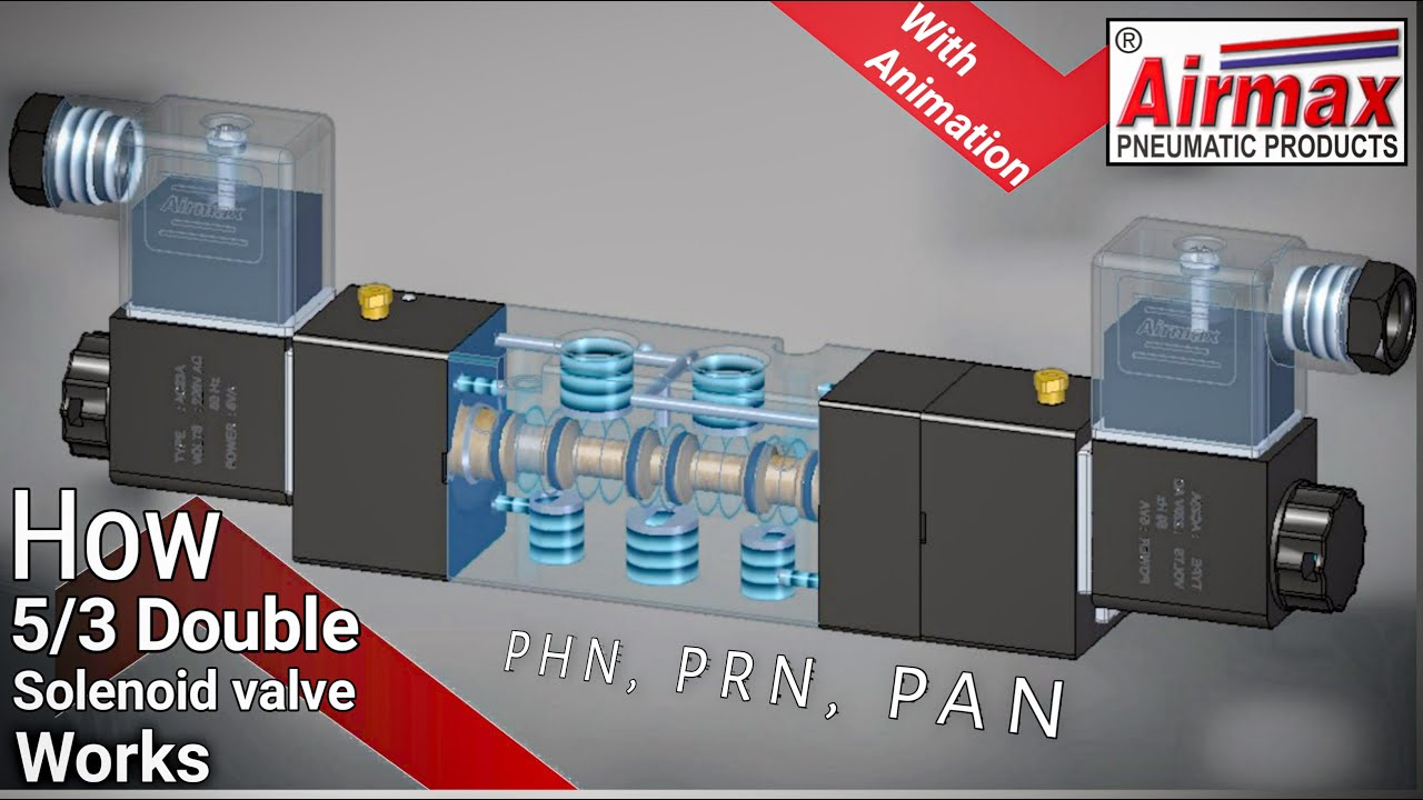
5/3 Solenoid Valve Working Priciple | 5/3 Directional Control Valve

using a 5 3 pressure center valve to control a through rod with
![[DIAGRAM] 3 Way Pneumatic Valve Diagram - MYDIAGRAM.ONLINE](https://i.ytimg.com/vi/kPULV_maM5E/maxresdefault.jpg)
[DIAGRAM] 3 Way Pneumatic Valve Diagram - MYDIAGRAM.ONLINE